Plan the capping stage in context
A capping machine that works alone may still create a bottleneck if the filler, conveyor, label applicator or packing stage has not been considered.

Line integration
Trigger capping usually sits between filling and labelling, but the project succeeds only when bottle transfer, cap feeding, machine controls and operator access are planned together.
Buyer route
Trigger capping usually sits between filling and labelling, but the project succeeds only when bottle transfer, cap feeding, machine controls and operator access are planned together.
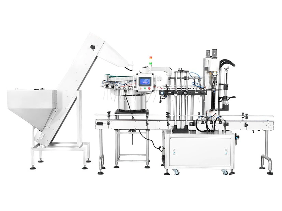
Specification notes
These are the practical factors that normally decide whether a simple capper, cap feeder, automatic trigger capper or integrated line is the right choice.
A capping machine that works alone may still create a bottleneck if the filler, conveyor, label applicator or packing stage has not been considered.
Key interfaces include conveyor height, bottle pitch, infeed and outfeed space, reject/inspection points, electrical supply, air supply and operator access for cap replenishment.
Some projects begin with a semi-automatic or compact capper and later add automatic feeding, extra conveyors or downstream equipment as demand grows.
Machine options
Use these product pages to compare the available machine families and then send Lancing your sample details for configuration advice.
Automatic trigger capping route for cleaning, home-care and chemical bottles with trigger sprayer closures.
View machine →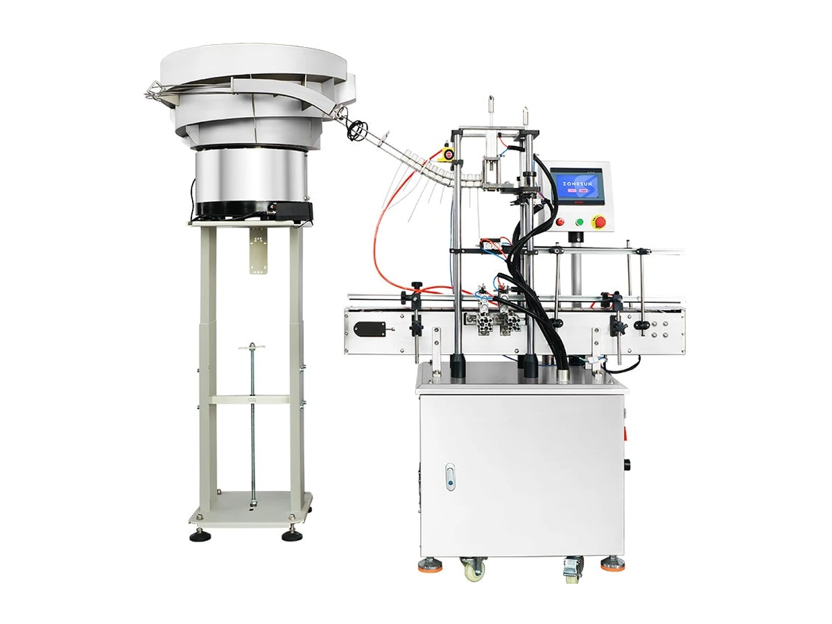
Cap feeding, orientation and dip-tube placement support for awkward trigger sprayer closures.
View machine →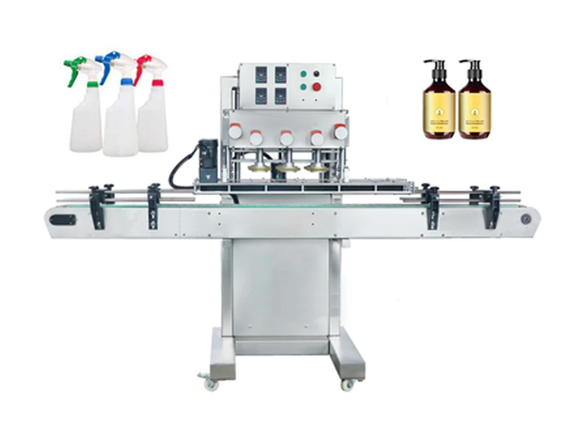
Inline belt/spindle capping route for higher-speed screw, spray and pump closure projects.
View machine →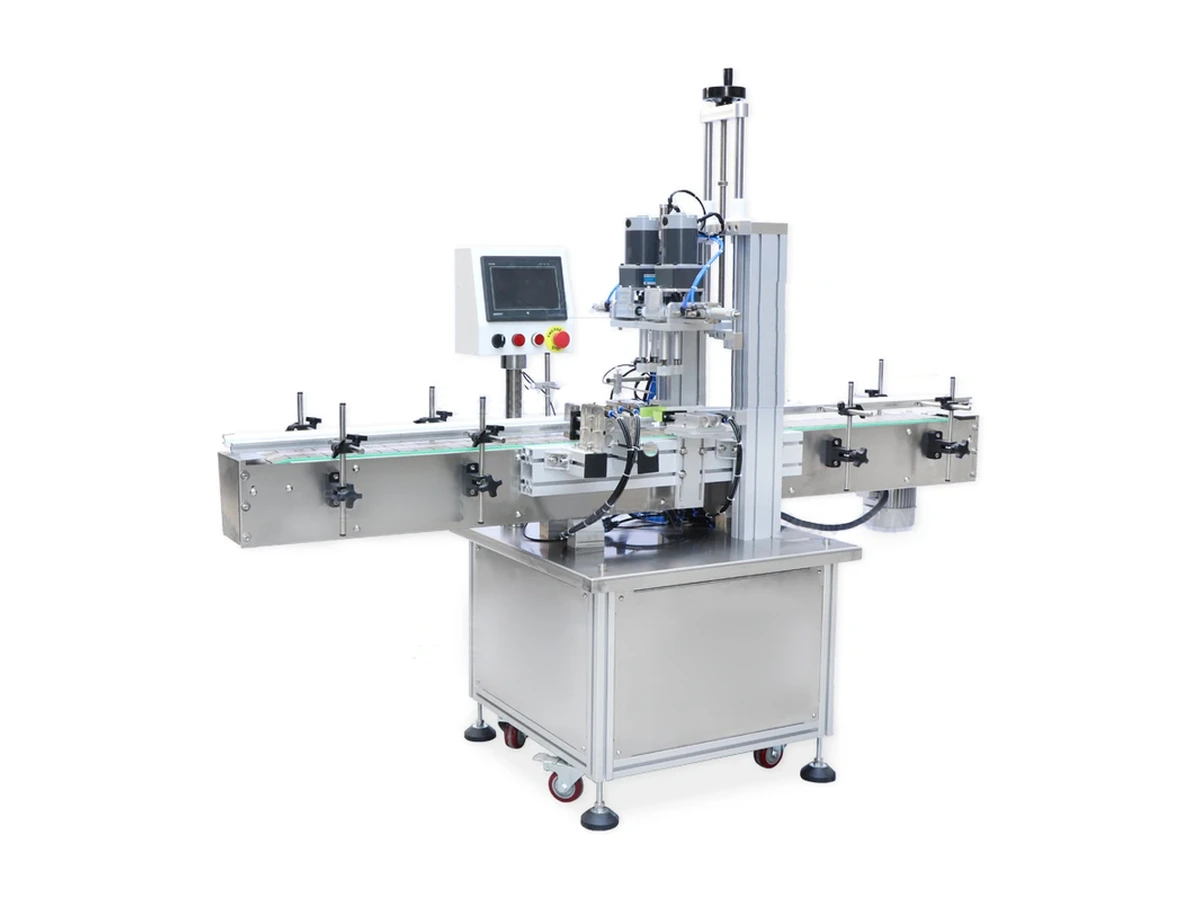
Pneumatic inline screw capper for spray, pump and screw-cap bottles with repeatable torque control.
View machine →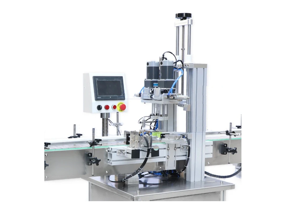
Space-saving screw capper for compact production areas, laboratories and lower-footprint lines.
View machine →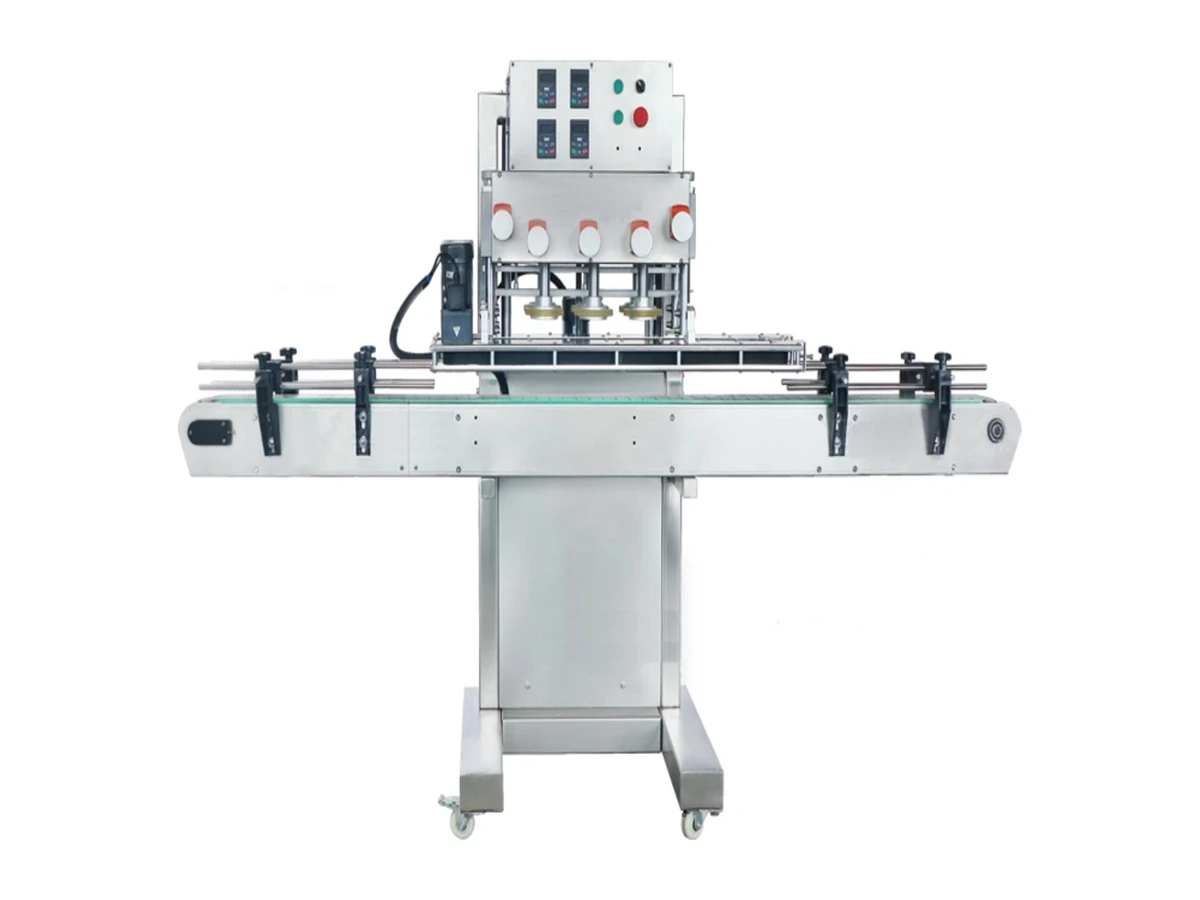
Semi-automatic capping route for smaller batches, early-stage projects and manual-assisted operation.
View machine →Related searches
These pages build the trigger-capping topic cluster and help users move from broad research into a machine enquiry.
Automatic trigger capper options for higher-output spray bottle lines. Compare cap feeding, orientation, placement, torque and conveyor integration.
Read page →Trigger cap feeder and spray cap orientation equipment for trigger sprayers with dip tubes. Plan bowl feeding, placement and capping integration.
Read page →Spray bottle capping machine options for trigger sprayers, pump closures and screw caps. Compare semi-automatic and automatic capping routes.
Read page →Trigger capper pricing guide for UK buyers. Understand what affects cost: cap feeding, automation level, output, tooling, installation and support.
Read page →FAQs
Often yes, but the current conveyor, filling speed, bottle spacing and control interfaces should be reviewed.
That depends on budget, output, future growth and whether you already have reliable filling or labelling equipment.
Yes. Lancing can support installation, commissioning and handover routes for packaging machinery projects.
Send the bottle, cap, tube length, output target and current line details. Lancing can help shortlist the right route.
Whole-line control
Mechanical fit is only one part of line integration. The trigger capper, feeder, conveyors, inspection and adjacent machines should share a documented operating sequence so that a short interruption does not create trapped tubes, mixed bottle states or an uncontrolled restart.
| Line area | Information exchanged or controlled | Integration question |
|---|---|---|
| Filling and upstream discharge | Machine ready, bottle available, stop request and any bottle that must not proceed to capping. | How is an incomplete or unsuitable bottle prevented from entering the trigger-placement sequence? |
| Infeed and bottle spacing | Conveyor availability, accumulation, bottle pitch, guide positions and the point at which a bottle becomes committed to the cycle. | What happens to bottles already between infeed control and the capping head when the line stops? |
| Closure feeder and buffer | Demand, low level, empty, blocked and fault states, plus control of recirculation during downstream stops. | How much normal variation can the buffer absorb, and when should closure supply stop? |
| Placement and tightening | Bottle present, closure present, cycle complete, capper fault and any condition that requires a bottle to be held or rejected. | How are uncertain bottles identified after an interrupted placement or tightening cycle? |
| Inspection and reject handling | Agreed checks, reject command, reject confirmation and the handling of a full reject container or unavailable reject device. | Can the line prove that a failed pack was removed rather than merely sending a reject signal? |
| Labelling and downstream packing | Ready, blocked or full state and the accumulation available between capping and the next constrained process. | Can the capper stop in a controlled sequence before bottles back up into the working station? |
| Restart and batch control | Reset authority, first bottle to inspect, affected-product boundary and the evidence retained for the event. | Which bottles are checked or removed before the line returns to normal automatic running? |
Each machine should have a clear ready condition. Running permission should depend on the required bottle, closure, guarding and downstream states rather than one general start signal.
Starved means the next required item is unavailable; blocked means the next process cannot accept output. Treating these as different states supports cleaner stopping and recovery.
A fault should identify the affected stage and the product boundary. After clearance, the line should return through defined checks rather than assuming every bottle in transfer remains acceptable.
Line acceptance should state the agreed bottle and trigger formats, closure-loading method, operator duties, replenishment pattern, run duration and quality criteria. Record accepted bottles, rejected packs, short stops, starvation, blockage and recovery events. A high mechanical cycle count is not useful if tube entry, thread start, cap height, torque or downstream handling creates rework.
Interface register
A line interface is complete only when the bottle or closure transfer, control state, affected-pack rule and restart sequence are all defined.
| Interface | Physical information | Control and acceptance information |
|---|---|---|
| Filler to capper | Conveyor height, bottle pitch, filled weight, spills/drips and accumulation. | Ready/starved/blocked signals, stop sequence and treatment of bottles held between machines. |
| Feeder to placement | Closure orientation, tube path, hand-off position and usable buffer. | Demand, low-level, jam, misorientation, shortage and restart logic. |
| Placement to tightening | Bottle location, cap seating, pre-threading and transfer stability. | Placement confirmation, incomplete-cycle handling and affected-pack identification. |
| Capper to inspection/reject | Bottle tracking, inspection position, reject path and confirmation sensor. | Defect categories, reject command, reject confirmation and accepted count. |
| Capper to labeller/packer | Trigger direction, bottle spacing, guide contact and accumulation. | Blocked response, restart order and presentation-quality rule. |
Use the controls and sensor guide for line states, the FAT and SAT checklist for interface tests and the quality guide for reject evidence.