Confirm component identity
Use supplier drawings where available and retain approved bottle, trigger and dip-tube samples. Record packaging condition and lot identity because tubes and closure bodies can change shape during transport or storage.

Compatibility guide
A trigger capping machine must be matched to the complete pack: bottle, neck finish, closure body, thread, dip tube, fill condition, required orientation and acceptable tooling contact.
Answer first
Bottle and trigger closure compatibility means the pack can be presented, supported, aligned, seated, threaded and tightened without unacceptable damage or variation. Cap diameter alone cannot establish that result. The neck finish, thread start, trigger-body shape, dip-tube behaviour, filled bottle stability, nozzle direction and tooling contact all need to be considered together.
The safest starting point is a controlled compatibility record for every proposed format. Use production-intent bottles and closures from the intended supplier and packaging condition. Record what is known, what must be trialled and which finished-pack checks will decide acceptance.
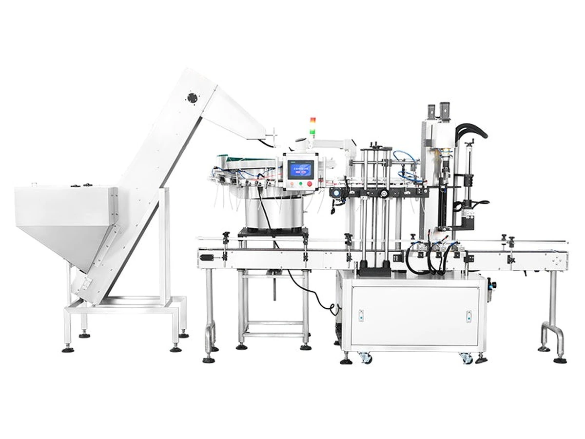
Compatibility record
The record should be detailed enough for another person to identify the same components and repeat the same checks.
| Interface | Information to record | Why it matters to machinery selection |
|---|---|---|
| Bottle body | Material, shape, height, base, shoulder, wall stiffness, filled weight and approved contact areas. | Determines conveyor guidance, side support, clamping and resistance to tightening torque without tipping, twisting or crushing. |
| Neck finish | Thread form, sealing features, neck height, damage limits and drawing revision where available. | Controls how the closure seats, starts and tightens. Similar outside diameters can use different threads or sealing geometry. |
| Trigger closure | Thread, body, actuator, nozzle direction, surface finish, moulding features and supplier revision. | Affects bulk feeding, orientation, gripping, placement, cosmetic contact and downstream presentation. |
| Dip tube | Reference point, total or usable length, outside diameter, material, end cut, curvature and attachment condition. | Affects bowl circulation, track clearance, tube entry, bottle-internal interference and risk of trapping or damage. |
| Fill and product condition | Empty or representative fill, mass, residue, drips, foaming and any safe handling limits. | Changes bottle stability, cleanliness, tooling contact and the practicality of inspection or functional testing. |
| Finished-pack requirement | Nozzle orientation, cap height, thread condition, approved torque or functional method, appearance and any downstream constraint. | Defines what an accepted pack is and which machine functions or inspection steps are required. |
Decision sequence
Use supplier drawings where available and retain approved bottle, trigger and dip-tube samples. Record packaging condition and lot identity because tubes and closure bodies can change shape during transport or storage.
Review bottle mouth, shoulder, trigger lever, nozzle and tube path. Identify where feeders, grippers, guides, side belts, chucks or spindle wheels may contact and what appearance standard applies.
Confirm that the dip tube enters without trapping, the closure sits squarely and the thread begins cleanly before final tightening. A cap that feels tight can still be high or cross-threaded.
Use the least stable filled format. Verify that bottle support resists torque without distortion and that the tightening method does not mark or move the trigger body beyond the approved condition.
Agree tube-entry, thread, cap-height, torque or functional, appearance and orientation checks. Record the measurement method and timing so results can be compared.
Selection boundaries
| Pack condition | Possible machinery implication | Evidence needed before approval |
|---|---|---|
| Trigger must reach a defined nozzle direction | Dedicated orientation, controlled placement or post-capping orientation may be required. | Orientation rule, tolerance, downstream reason and representative closure trial. |
| Long or flexible dip tube | Tube straightening, guidance, controlled hand-off or a dedicated placement sequence may be required. | Production tube samples, agreed length reference and tube-damage inspection. |
| Light, tall or shaped bottle | Side belts, clamps, neck support or lower-complexity operator-assisted handling may be more suitable. | Filled samples, least-stable format and approved contact areas. |
| Closure is not pre-seated | A cap feeder, pick-and-place or pre-threading station may be needed before spindle or chuck tightening. | Bulk presentation trial, placement result and clean thread-start evidence. |
| Several closure families share one line | Change parts, recipes, adjustable tooling or separate machine routes may be required. | Complete format matrix, changeover plan and first-off approval method. |
Buyer questions
No. Cap diameter does not define thread form, neck finish, trigger-body geometry, dip-tube behaviour, placement height, surface condition or bottle stability. Use drawings and production samples to assess the complete pack and the way it will be fed, supported and tightened.
Bottle material is one factor, but shape, wall stiffness, filled weight, base, shoulder, neck finish and acceptable contact matter as well. Two HDPE or PET bottles may behave differently under side-belt or clamp pressure, so the actual filled formats should be tested.
Filled weight changes stability, conveyor behaviour and the force needed to prevent rotation. Product residue or drips can also affect cleanliness and grip. Use the real product where safe and agreed, or an approved substitute that reproduces the relevant mass and handling condition.
It may be possible when the machine, tooling and settings can accommodate each bottle and closure combination. Do not assume compatibility from similar dimensions. List every neck finish, identify required parts or adjustments and prove clean placement, thread start and finished-pack quality at changeover.
Yes. Residue on the neck, bottle or tooling can affect thread engagement, grip, cleanliness and inspection. The line layout should control drips or splash from filling, and the trial should include realistic pack condition where the product can be handled safely.
Retain component identities, drawings where available, approved samples, format matrix, critical measurements, photographs of contact or clearance points, trial settings and the finished-pack acceptance method. Record any limitations or supplier-dependent conditions so later component changes can be reviewed.
Next, build the trigger capping sample trial matrix, confirm incoming component checks and use the machine selection guide.
Send production-intent bottles, closures, dip-tube details, target output and the proposed format range for project-specific guidance.